![[Mailbox]](/www_images/mail.gif)
Any questions and comments:
Michiko Masutani.
(301)763-8000 Ext.7254
Kenneth A.Campana.
(301)763-8000 Ext.7228
NCEP OSSE Project / Last Modified October 20 1999
Note on Cloud Cover of the ECMWF Nature run
used for OSSE/NPOESS project
Office Note 427
Michiko Masutani, Kenneth A. Campana, Stephen J. Lord
EMC/NCEP/NWS/NOAA
Shi-Keng Yang
CPC/NCEP/NWS/NOAA
October, 1999
Word perfect version of the report
Table 1 Area averaged cloud cover over (10S-10N, 150E-180E).
Figures
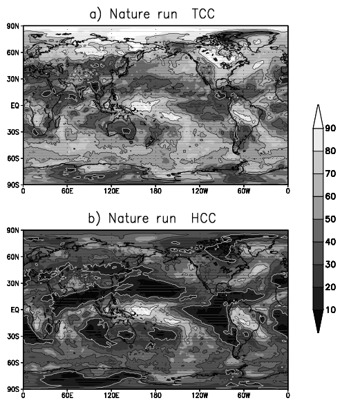
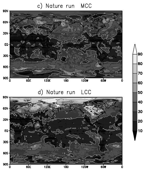
Fig.1 NR cloud averaged for the NR period. a)TCC b) HCC, c) MCC d)LCC, contour interval 20%.
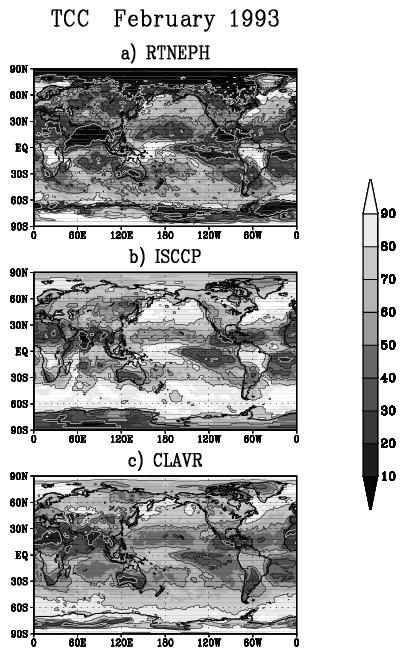
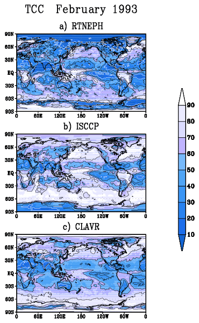
Fig.2 Observed estimated total cloud cover during February 1993 (a)RTNEPH, (b) ISCCP, and (c) CLAVR. Contour interval 20%. (Colored figures)
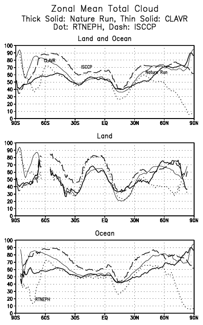
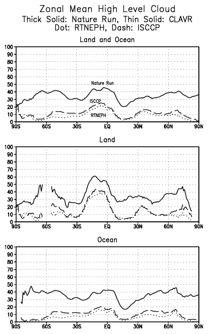
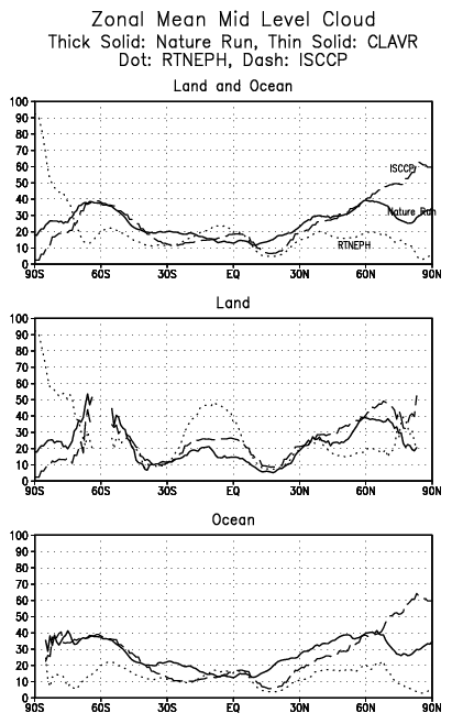
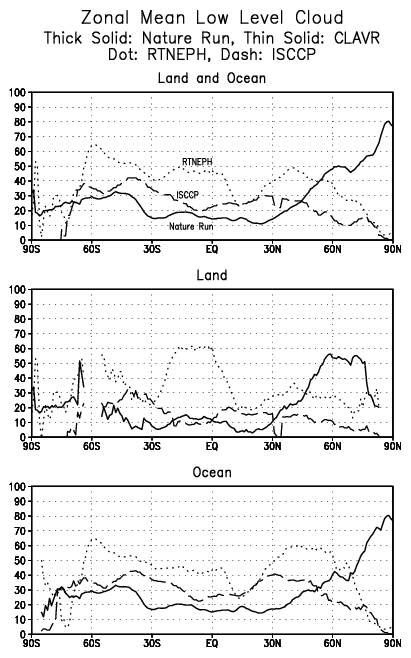
Fig.3 a) Zonal mean of TCC, NR(solid), RTNEPH (dot), ISCCP (short dash), CLAVR (long dash). Top: include land and ocean, Midlle: over land only, Bottom: over ocean only. (b) Same as (a) but for zonal mean of HCC. (c)Same as (a) but for zonal mean of MCC. (d)Same as (a) but for zonal mean of LCC. CLAVR is included only in TCC.
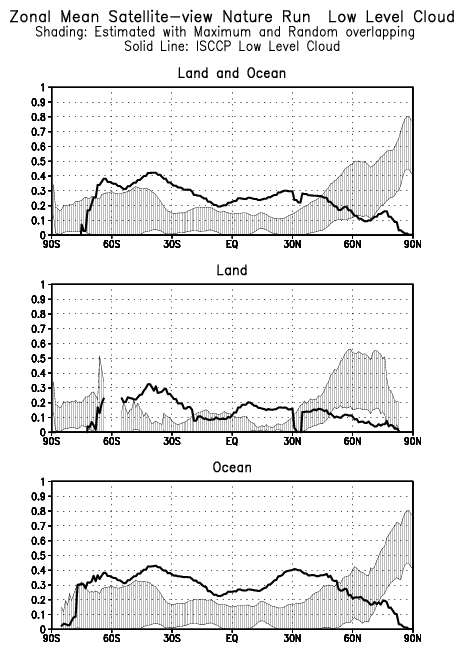
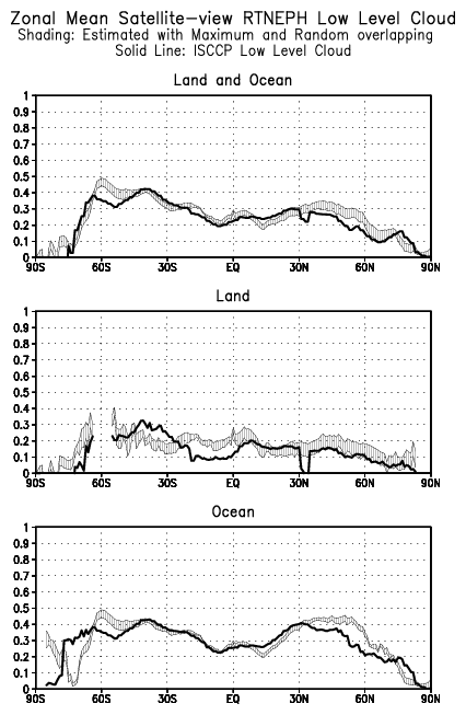
Fig.4 Zonal mean satellite-view LCC. Top: include land and ocean, Middle: land only, Bottom: ocean only. Solid line is ISCCP cloud. a) Shading: satellite view NR cloud max over lapping and random overlapping. b) Shading: satellite-view RTNEPH cloud.
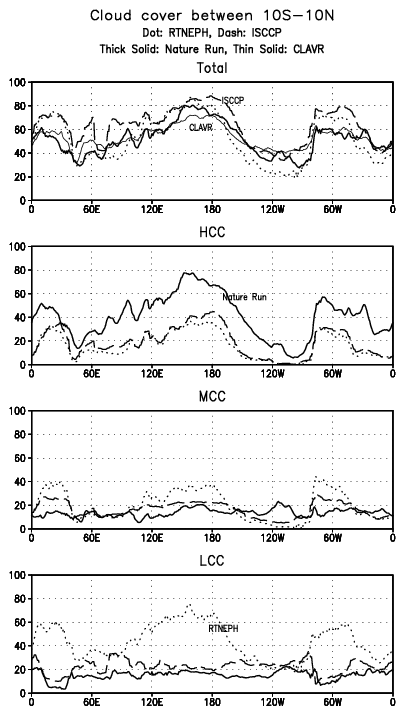
Fig.5 Cloud cover averaged between 10S to 10N. For both over the land and ocean. NR(solid), RTNEPH (dot), ISCCP (short dash), CLAVR (long dash). From top, TCC, HCC, MCC, and LCC. CLAVR is included only in TCC.
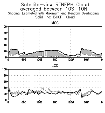
Fig.6 The satellite-view MCC (Top) and LCC (bottom) averaged between 10S to 10N. Solid line is ISCCP cloud. a) Shading: satellite-view NR cloud max over lapping and random overlapping. b) Shading: satellite-view RTNEPH cloud.
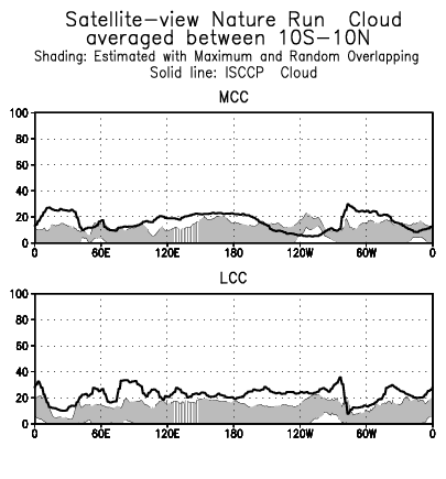
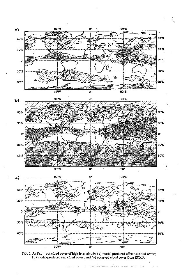
Fig.7 Figure from Tiedtke (1993). (a) model high level cloud (b) model effective cloud (c) ISCCP high level cloud.
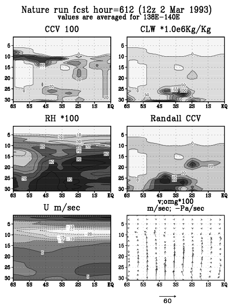
Fig.8 Cross section for CCV, CLW, relative humidity(RH), CCV computed using Randal formula (CCV_R), zonal wind (U), and meridional wind (V) and . Values are averaged between 138E and 140E. Name of the values are indicated as subtitle. Contour intervals are 20% for CCV, 50x10-6 Kg/Kg for CLW, 10% for RH, 20% for CCV, 5ms-1 for zonal wind. Factor 100 is multiplied to to plot with meridional wind V.
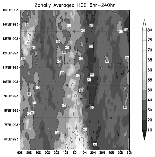
Fig.9 Time -latitude section of zonally averaged nature run HCC.
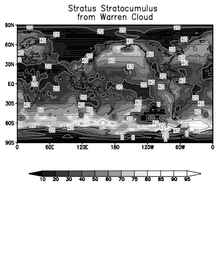
Fig.10 Stratus and Strato cumulus in Warren cloud DJF climatology.
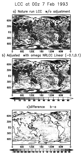
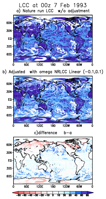
Fig.11 Snap shot the Nature run LCC at 00Z 7 February 1993 a) Adjusted b) without adjustment. c) the difference between b and a.(Colored figures.)
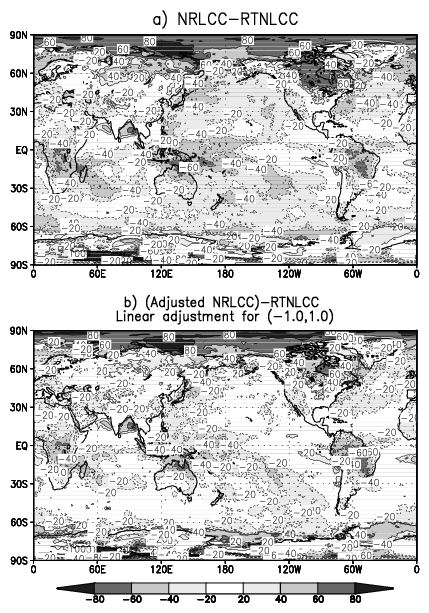
Fig.12 The difference between time averaged LCC for NR and LCC for February 93 RTNEPH. a) without adjustment (NRLCC-RTNEPH), b) Adjusted (NRLCCadj - RTNEPH)
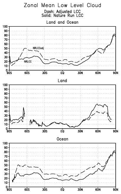
Fig. 13 Zonal mean LCC. Solid line: without adjustment (NRLCC). Dashed line: with adjustment (NRLCCadj).
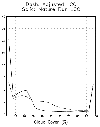
Fig. 14 Frequency distribution for ocean areas containing cloud cover in 20, 5%-band, categories. Solid line: without adjustment (NRLCC). Dashed line: with adjustment (NRLCCadj).
NCEP OSSE Project / Last Modified October 20 1999